















Relays Shelly wiring diagrams
Shelly Plus Uni wiring diagram
How to wire a Shelly Plus Uni to pulse a garage door opener, powered from the motor's own 12 or 24 V accessory supply.
Wiring diagrams
The motor's accessory supplyShelly Plus Uni
Circuit overview
Motor supply0 VDry contact
Everything on the Uni is low voltage, from the motor's own 12 or 24 V supply. Its outputs switch 30 V and 300 mA at most, so they only go on a low-voltage trigger input.
Showing the whole circuit
How it's wired, terminal by terminal
-
Pulse a garage door opener
Dry contact to the opener's trigger input
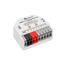
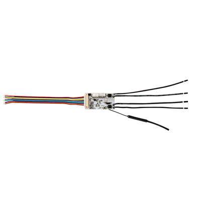
The Uni runs off the motor's own 12 or 24 V accessory supply on its red and black leads, so no mains goes near it. The two OUT1 screws close briefly across the motor's pushbutton terminals, either way round. In the Shelly app, turn on Auto off for the output with a short delay.
Terminals for pulse a garage door opener on the Shelly Plus Uni Terminal What it does here OUT1 Dry contact, one trigger terminal OUT1 Dry contact, the other trigger terminal VAC1 Red lead, from the motor's 12 or 24 V supply VAC2 Black lead, the supply's 0 V OUT2 is a second contact for another door or gate. The other leads (inputs and sensor connections) aren't used here; tape their ends.
Supply: The motor's accessory supply
More wiring diagrams
Still need a hand?
We answer most messages within one business day. If your question is about an existing order, have your order number ready. It speeds things up.
Contact us