














Relays Shelly wiring diagrams
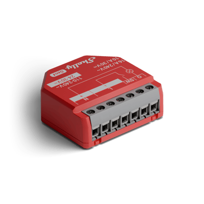
Shelly 1PM Gen4 and Gen3 wiring diagram
How to wire a Shelly 1PM to switch and meter a light, an exhaust fan or an appliance, with your wall switch on SW.
Wiring diagrams
230 V~ 50 HzShelly 1PM Gen4
Circuit overview
1Light / appliance2Wall switch
Active (supply)Neutral / 0 VSwitched loadSwitch signal / dry contact
In Australia, fixed 230 V wiring is licensed-electrician work. Use these diagrams to plan the job and brief your electrician.
Showing the whole circuit
Every job, terminal by terminal
The Shelly 1PM Gen3 is wired the same way as the Shelly 1PM Gen4.
-
Switch a light or appliance
One measured circuit, switched through O
Mains comes in on L and N, and O carries the switched active out to the light while the relay meters the power it draws. The existing wall switch lands on SW, so the physical switch keeps working alongside the app.
Terminals for switch a light or appliance on the Shelly 1PM Gen4 Terminal What it does here L 230 V active in (any of the three L terminals) N Neutral in (either N terminal) O Switched, metered active out to the light or appliance SW Existing wall switch L/N Spare supply terminals, the strip carries three L and two N inputs Supply: 230 V~ 50 Hz
-
Switch an exhaust fan
The fan's circuit, measured and switched through O
Mains comes in on L and N, and O carries the switched active out to the fan while the relay meters what it draws. The fan's wall switch lands on SW, so it still turns the fan on and off. Shelly lists fans as inductive loads that need an RC snubber across the load.
Terminals for switch an exhaust fan on the Shelly 1PM Gen4 Terminal What it does here L 230 V active in (any of the three L terminals) N Neutral in (either N terminal) O Switched, metered active out to the fan SW The fan's wall switch L/N Spare supply terminals, the strip carries three L and two N inputs Supply: 230 V~ 50 Hz
-
Meter an appliance
Same circuit, read as an energy monitor
The wiring is identical — the point of this setup is the meter. Put a heater, towel rail or pool pump on O and the relay reports its live power draw and energy use in the app, with the switch as a bonus. A pump or other motor needs an RC snubber across the load.
Terminals for meter an appliance on the Shelly 1PM Gen4 Terminal What it does here O The metered appliance, heater, towel rail, pump (a motor needs an RC snubber) L 230 V active in (any of the three L terminals) N Neutral in (either N terminal) SW Optional wall switch L/N Spare supply terminals, the strip carries three L and two N inputs Supply: 230 V~ 50 Hz
More wiring diagrams
Still need a hand?
We answer most messages within one business day. If your question is about an existing order, have your order number ready. It speeds things up.
Contact us