














Relays Shelly wiring diagrams
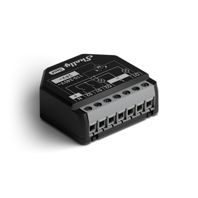
Shelly 2PM Gen4 and Gen3 wiring diagram
How to wire a Shelly 2PM for two lights, a roller shutter or awning in cover mode, or a bathroom light and exhaust fan.
Wiring diagrams
230 V~ 50 HzShelly 2PM Gen4
Circuit overview
1Light 12Light 23Switch 14Switch 2
Active (supply)Neutral / 0 VSwitched loadSwitch signal / dry contact
In Australia, fixed 230 V wiring is licensed-electrician work. Use these diagrams to plan the job and brief your electrician.
Showing the whole circuit
Every job, terminal by terminal
The Shelly 2PM Gen3 is wired the same way as the Shelly 2PM Gen4.
-
Switch two lights
Two circuits, one relay
Each channel is its own switched, metered circuit: O1 carries the first light, O2 the second, and the wall switches land on S1 and S2. Mains comes in once on L and N and feeds both.
Terminals for switch two lights on the Shelly 2PM Gen4 Terminal What it does here O1 Switched, metered active out to the first light O2 Switched, metered active out to the second light S1 Wall switch for channel 1 S2 Wall switch for channel 2 L 230 V active in (either L terminal) N Neutral in Supply: 230 V~ 50 Hz
-
Drive a roller shutter or awning
Cover mode — one motor, two directions
In cover mode the relay drives the motor one way at a time: O1 and O2 each feed one winding, and the motor's common returns to neutral. If the motor runs the wrong way, turn on Reverse directions before calibrating. S1 and S2 take optional open and close buttons. Use a motor with its limit switches set before connecting it.
Terminals for drive a roller shutter or awning on the Shelly 2PM Gen4 Terminal What it does here O1 One motor winding O2 The other motor winding N Neutral in, also the motor's common return L 230 V active in (either L terminal) S1 Optional open button S2 Optional close button Supply: 230 V~ 50 Hz
-
Run a bathroom light and exhaust fan
Light on O1, fan on O2
The light and the exhaust fan each get their own channel, so the relay knows when the light goes off and can keep the fan running long enough to clear the steam. O1 feeds the light, O2 the fan, and the two wall switches land on S1 and S2. Active feeds both L terminals, as Shelly's ANZ diagram shows. The fan is an inductive load, which Shelly's ANZ load list qualifies as needing an RC snubber, so that is one for your electrician.
Terminals for run a bathroom light and exhaust fan on the Shelly 2PM Gen4 Terminal What it does here O1 Switched, metered active out to the light O2 Switched, metered active out to the exhaust fan S1 Light switch S2 Fan switch L 230 V active in, to both L terminals N Neutral in Supply: 230 V~ 50 Hz
More wiring diagrams
Still need a hand?
We answer most messages within one business day. If your question is about an existing order, have your order number ready. It speeds things up.
Contact us