















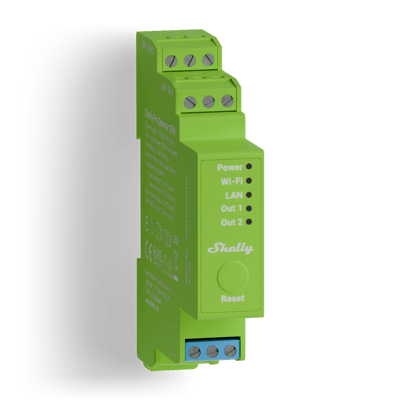
Dimmers Shelly wiring diagrams
Shelly Pro Dimmer 2PM wiring diagram
How to wire a Shelly Pro Dimmer 2PM in the switchboard to dim one or two lights, each with its own push buttons.
Wiring diagrams
230 V~ 50 HzShelly Pro Dimmer 2PM
Circuit overview
1Push button2Dimmable light
Active (supply)Neutral / 0 VSwitched loadSwitch signal / dry contact
In Australia, fixed 230 V wiring is licensed-electrician work. Use these diagrams to plan the job and brief your electrician.
Showing the whole circuit
How it's wired, terminal by terminal
-
Dim a light
One dimmed circuit on channel 1, with a second channel spare
The dimmer sits on a DIN rail in the switchboard. Mains comes in on L and N, and O1 carries the dimmed active out to the light. A push button on SW1 switches the light with a press and dims it while held. O2, with its buttons on SW3 and SW4, can dim a second light the same way. Dimmable lights only, up to 200 W a channel.
Terminals for dim a light on the Shelly Pro Dimmer 2PM Terminal What it does here L 230 V active in (either L terminal) N Neutral in O1 Dimmed active out to the light (channel 1) SW1 Push button: press to switch, hold to dim SW2 Second button input for channel 1 O2 Channel 2 dimmed output, for a second light SW3 Channel 2 button input SW4 Channel 2 second button input Supply: 230 V~ 50 Hz
More wiring diagrams
Still need a hand?
We answer most messages within one business day. If your question is about an existing order, have your order number ready. It speeds things up.
Contact us