
















Inputs & add-ons Shelly wiring diagrams
Shelly Plus Add-on wiring diagram
How to wire a soil moisture sensor or a DS18B20 temperature probe to the Shelly Plus Add-on.
Wiring diagrams
3.3 V from the ShellyShelly Plus Add-on
Circuit overview
Brown: power (VCC)White: ground (GND)Yellow: moisture (ANALOG IN)Green: temperature, not connected
In Australia, fixed 230 V wiring is licensed-electrician work. Use these diagrams to plan the job and brief your electrician.
Showing the whole circuit
Every job, terminal by terminal
-
Wire a soil moisture sensor
Wire a soil moisture sensor
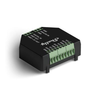
An analogue soil moisture sensor takes three wires, shown here in the Truebner SMT50's colours. Brown, the sensor's supply, goes to VCC on the 1-Wire side. White goes to GND, and yellow, the moisture output, to ANALOG IN on the other side. The green wire is the SMT50's temperature output: leave it unconnected unless you want to read temperature instead. Only the three terminals in use are drawn; the Add-on has more on both sides.
Terminals for wire a soil moisture sensor on the Shelly Plus Add-on Terminal What it does here VCC Sensor power, 3.3 V: brown on the SMT50 GND Ground: white on the SMT50 ANALOG IN Moisture output, 0 to 10 V: yellow on the SMT50 Not used for this sensor, so not drawn: the other VCC, DATA and GND terminals on the 1-Wire side, and DIGITAL IN, VREF OUT and VREF+R1 OUT on the analogue side.
Supply: 3.3 V from the Shelly
See the soil moisture watering guide -
Wire a DS18B20 temperature probe
Wire a DS18B20 temperature probe
A DS18B20 probe has three wires, all on the Add-on's 1-Wire side. Red, the probe's supply, goes to VCC, yellow, the data line, to DATA, and black to GND. The 1-Wire side has three sets of VCC, DATA and GND, joined on the board, so any set works, and up to five probes can share them. Only the three terminals in use are drawn.
Terminals for wire a ds18b20 temperature probe on the Shelly Plus Add-on Terminal What it does here VCC Probe power, 3.3 V: red DATA 1-Wire data: yellow GND Ground: black Not used for one probe, so not drawn: the other two sets of VCC, DATA and GND on the 1-Wire side, and everything on the analogue side.
Supply: 3.3 V from the Shelly
See the roof-space fan guide
More wiring diagrams
Still need a hand?
We answer most messages within one business day. If your question is about an existing order, have your order number ready. It speeds things up.
Contact us