
















LED controllers Shelly wiring diagrams
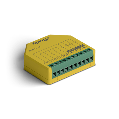
Shelly Plus RGBW PM wiring diagram
How to wire a Shelly Plus RGBW PM to run RGBW deck lights from a 12 or 24 V power supply.
Wiring diagrams
12 or 24 V DC power supplyShelly Plus RGBW PM
Circuit overview
+12 or 24 V0 VColour and white channels
Everything on this controller is low voltage from a 12 or 24 V DC power supply. Unplug the supply before you move a wire.
Showing the whole circuit
How it's wired, terminal by terminal
-
Run RGBW deck lights
Run RGBW deck lights
The 12 or 24 V power supply lands on + and ⊥. The deck lights' common V+ joins the supply positive, and their R, G, B and W wires go to the matching outputs. The inputs I1 to I4 take optional switches or buttons and aren't used here.
Terminals for run rgbw deck lights on the Shelly Plus RGBW PM Terminal What it does here + Positive from the power supply, and the lights' common V+ ⊥ Negative from the power supply R Red channel G Green channel B Blue channel W White channel I1 Optional switch or button I2 Optional switch or button I3 Optional switch or button I4 Optional switch or button I1 to I4 take optional switches or buttons for local control.
Supply: 12 or 24 V DC power supply
See the smart deck lights guide
More wiring diagrams
Still need a hand?
We answer most messages within one business day. If your question is about an existing order, have your order number ready. It speeds things up.
Contact us